Industrial Automation
 Not available

 Not available
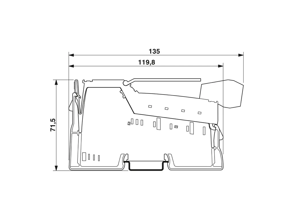
 | Dimensions | Dimensional drawing: https://dam-mdc.phoenixcontact.com/rendition/156443151564/20a984302842e949b5ce7beb58df3766/-S204x204-FJPG Width: 48.8 mm Height: 135 mm Depth: 71.5 mm |
| Notes | Utilization restriction EMC note: EMC: class A product, see manufacturer's declaration in the download area |
| Interfaces | INTERBUS Number of interfaces: 2 Connection method: Inline shield connector Transmission speed: 2 Mbps Transmission physics: Copper Remote bus branch / Inline local bus Number of interfaces: 1 Connection method: Inline data jumper Transmission speed: 2 Mbps |
| System properties | System limits Number of local bus devices that can be connected: max. 63 Number of devices with parameter channel: max. 62 Number of supported branch terminals with remote bus branch: max. 15 Module ID code (dec.): 04 ID code (hex): 04 Length code (hex): 00 Length code (dec): 00 Process data channel: 0 bit Input address area: 0 bit Output address area: 0 bit Register length: 0 bit |
| Product properties | Type: modular Product type: I/O component Product family: Inline Scope of delivery: including Inline connectors and marking fields Diagnostics messages: I/O error yes, if the segment voltage US is not present |
| Electrical properties | Maximum power dissipation for nominal condition: 30 W Protective circuit: Short-circuit protection of the communications power; electronic Short-circuit protection of the analog supply; electronic Surge protection (segment supply, main supply, bus coupler supply); Input protective diodes (can be destroyed by permanent overload)Pulse loads up to 1500ÃW are short circuited by the input protective diode. Protection against polarity reversal (segment supply/main supply); Parallel diodes for protection against polarity reversal; in the event of an error the high current flowing through the diodes causes the fuse connected upstream to blow. Protection against polarity reversal (bus coupler supply); Serial diode in the lead path of the power supply unit; in the event of an error only a low current flows. In the event of an error, no fuse trips within the external power supply unit. Potentials: Bus coupler supply U Supply voltage: 24 VÃDC (via Inline connector) Supply voltage range: 19.2 VÃDC ... 30 VÃDC (including all tolerances, including ripple) Current draw: max. 1.25 A (with max. number of connected I/O terminal blocks) typ. 100 mA (without connected Inline I/O terminals) Potentials: Communications power (U Supply voltage: 7.5 VÃDC ñ5Ã% Potentials: Supply of analog modules (U Supply voltage: 24 VÃDC Supply voltage range: 19.2 VÃDC ... 30 VÃDC (including all tolerances, including ripple) Potentials: Main circuit supply (U Supply voltage: 24 VÃDC Supply voltage range: 19.2 VÃDC ... 30 VÃDC (including all tolerances, including ripple) Potentials: Segment circuit supply (U Supply voltage: 24 VÃDC Supply voltage range: 19.2 VÃDC ... 30 VÃDC (including all tolerances, including ripple) Electrical isolation/isolation of the voltage ranges Test voltage: 5 V supply, incoming remote bus / 5 V supply outgoing remote bus: 500 VÃAC, 50 Hz, 1 min. Test voltage: 5 V supply incoming remote bus / 7.5 V communications power, 24 V analog supply, 24 V bus coupler supply: 500 VÃAC, 50 Hz, 1 min. Test voltage: 5 V supply, incoming remote bus / 24 V main supply, 24 V segment supply: 500 VÃAC, 50 Hz, 1 min. Test voltage: 5ÃV supply incoming remote bus / functional ground: 500 VÃAC, 50 Hz, 1 min. Test voltage: 5 V supply outgoing remote bus / I/O (UM, US): 500 VÃAC, 50 Hz, 1 min. Test voltage: 5 V supply outgoing remote bus / communications power (UBK, UL, UANA): 500 VÃAC, 50 Hz, 1 min. Test voltage: 5ÃV supply outgoing remote bus / functional ground: 500 VÃAC, 50 Hz, 1 min. Test voltage: 7.5ÃV communications power, 24ÃV analog supply, 24ÃV bus coupler supply/functional ground: 500 VÃAC, 50 Hz, 1 min. Test voltage: Communications power (UBK, UL, UANA) / I/O (UM, US): 500 VÃAC, 50 Hz, 1 min. Test voltage: 24ÃV main supply, 24ÃV segment supply/functional ground: 500 VÃAC, 50 Hz, 1 min. |
| Connection data | Connection technology Connection name: Inline connector Conductor connection Connection method: Spring-cage connection Conductor cross section rigid: 0.08 mm² ... 1.5 mm² Conductor cross section flexible: 0.08 mm² ... 1.5 mm² Conductor cross section AWG: 28 ... 16 Stripping length: 8 mm Inline connector Connection method: Spring-cage connection Conductor cross section, rigid: 0.08 mm² ... 1.5 mm² Conductor cross section, flexible: 0.08 mm² ... 1.5 mm² Conductor cross section AWG: 28 ... 16 Stripping length: 8 mm |
| Environmental and real-life conditions | Ambient conditions Ambient temperature (operation): -25°C ... 55°C Degree of protection: IP20 Air pressure (operation): 70 kPa ... 106 kPa (up to 3000Ãm above sea level) Air pressure (storage/transport): 70 kPa ... 106 kPa (up to 3000Ãm above sea level) Ambient temperature (storage/transport): -25°C ... 85°C Permissible humidity (operation): 10 % ... 95 % (non-condensing) Permissible humidity (storage/transport): 10 % ... 95 % (non-condensing) |
| Standards and regulations | Protection class: III (IEC 61140, ENÃ61140, VDEÃ0140-1) |
| Mounting | Mounting type: DIN rail mounting |
Description other products


