Automazione Industriale

Meccatronica

Sicurezza Industriale

Componenti Quadri

Sensori e Sistemi di Visione

Pneumatica

Network e Comunicazione

Cavi Speciali

Software di progettazione

Accedi ai servizi

Entra nella tua area riservata

Accedi ai servizi

Entra nella tua area riservata

PHOENIX CONTACT 2907921
PHOENIX CONTACTNon disponibile

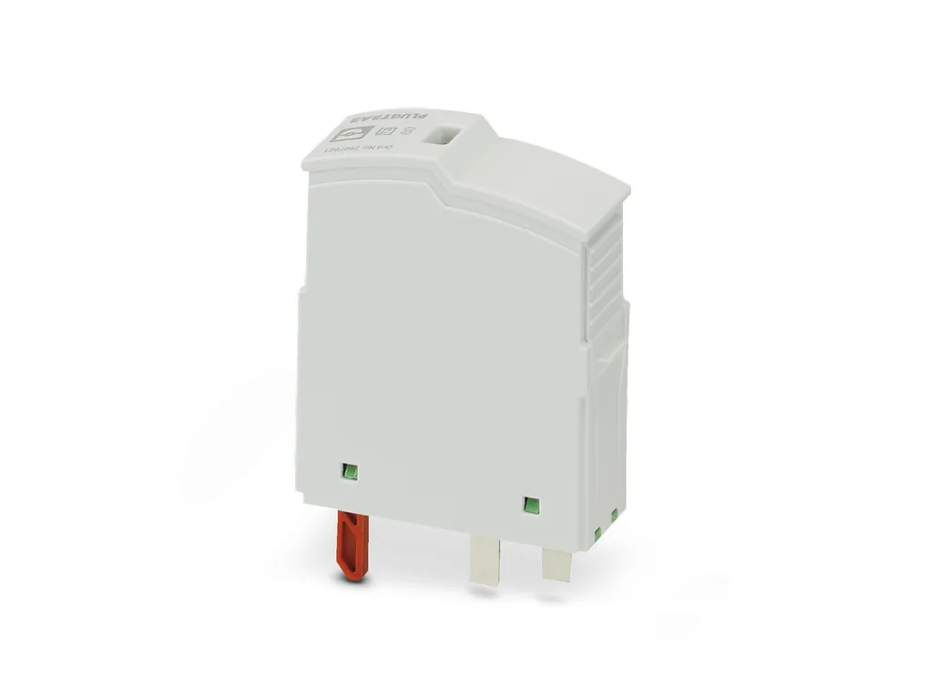
PLT-SEC-T3-60-P-UT/PT - Type 3 surge protection plug

Replacement plug for type 3 surge protection from the PLT-SEC-…-UT/PT product series. Nominal voltage 60V.
Cod. Articolo: 2907921
Cod. Fornitore: 2907921
PHOENIX CONTACT


Diminuisci la quantità
Aumenta la quantità
Caratteristiche Tecniche
Download
Caratteristiche Tecniche
Product propertiesIEC power supply system: TN-S
Type: Male
Product type: Replacement plug
Product family: SEC Family
Number of positions: 2
Surge protection fault message: optical
Insulation characteristics
Overvoltage category: III
Pollution degree: 2
IEC test classification: III
T3
EN type: T3
Number of ports: One
Connection dataConnection method: pluggable
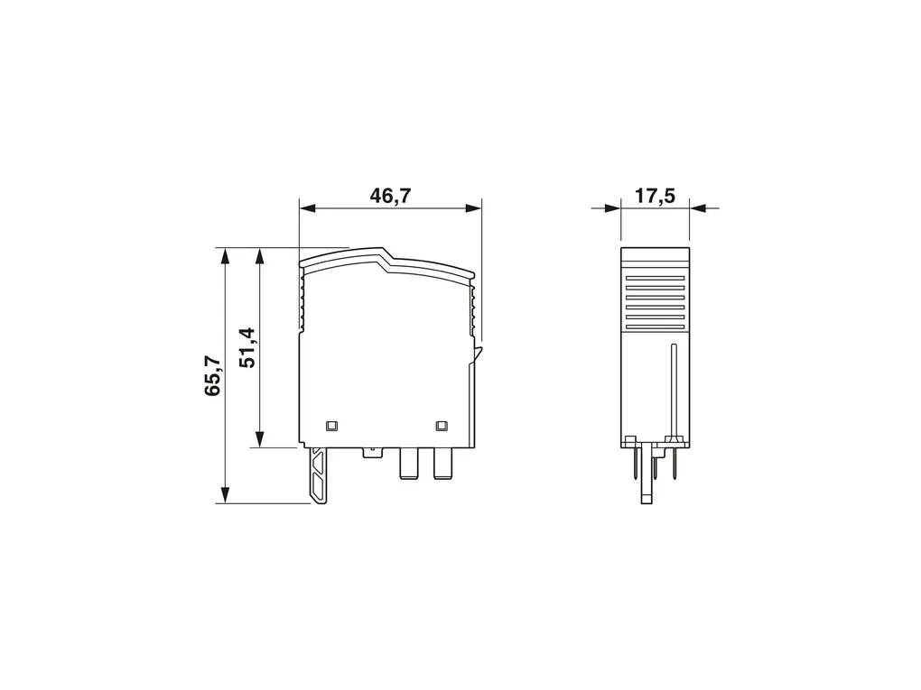
DimensionsDimensional drawing: https://dam-mdc.phoenixcontact.com/rendition/156443151564/25e5299f9f2d3a47963ae1591d8c2c5d/-S204x204-FJPG
Width: 17.5 mm
Height: 46.7 mm
Depth: 65.7 mm
Horizontal pitch: 1 Div.
Material specificationsFlammability rating according to UL 94: V-0
CTI value of material: 600
Insulating material: PA 6.6-FR 20 % GF
PA 6.6-FR
Housing material: PA 6.6-FR 20Â% GF
PA 6.6-FR
Protective circuitMode of protection: L-N
L-PE
N-PE
Direction of action: 1L-N & N-PE
Nominal voltage UN: 60ÂVÂACÂ(TN-S)
Nominal frequency fN: 50 Hz (60ÂHz)
Maximum continuous voltage UC: 80 VÂAC
Residual current IPE: ≤ 5 µA
Standby power consumption PC: ≤ 5.3 mVA (at UREF)
≤ 8.4 mVA (at UC)
Reference test voltage UREF: 66 VÂAC
Nominal discharge current In (8/20) µs: 2 kA
Combination wave UOC: 4 kV
Voltage protection level Up (L-N): ≤ 0.48 kV
Voltage protection level Up (L-PE): ≤ 0.8 kV
Voltage protection level Up (N-PE): ≤ 0.8 kV
TOV behavior at UT (L-N): 120 VÂAC (120Âmin / safe failure mode)
TOV behavior at UT (L-PE): 120 VÂAC (120Âmin / withstand mode)
Response time tA (L-N): ≤ 25 ns
Response time tA (L-PE): ≤ 100 ns
Response time tA (N-PE): ≤ 100 ns
Short-circuit current rating ISCCR: 10 kA AC
Max. backup fuse with branch wiring: 32 A (gG / B / C)
Additional technical data
Short-circuit current rating ISCCR: 0.25 kA DC (Without additional backup fuse in the DC branch wiring)
5 kA DC (for 20 A gG / B backup fuse)
Maximum discharge current Imax (8/20) µs: 4 kA
Residual voltage Ures (L-N): ≤ 0.42 kV (at 1 kA)
≤ 0.48 kV (at 2 kA)
≤ 0.4 kV (at UOC = 2 kV)
Residual voltage Ures (L-PE): ≤ 0.55 kV (at 1 kA)
≤ 0.6 kV (at 2 kA)
≤ 0.6 kV (at UOC = 2 kV)
Residual voltage Ures (N-PE): ≤ 0.55 kV (at 1 kA)
≤ 0.6 kV (at 2 kA)
≤ 0.6 kV (at UOC = 2 kV)
Maximum continuous voltage UC: 80 VÂDC
Mode of protection: (DC+) - (DC-)
(DC+/DC-) - PE
Environmental and real-life conditionsAmbient conditions
Degree of protection: IP20
Ambient temperature (operation): -40°C ... 80°C
Ambient temperature (storage/transport): -40°C ... 80°C
Altitude: ≤ 6000 m (amsl)
Permissible humidity (operation): 5 % ... 95 %
Shock (operation): 30g (Half-sine / 11 ms / 3x ±X, ±Y, ±Z)
Vibration (operation): 5g (5Â...Â500ÂHz / 2.5Âh / X, Y, Z)
ApprovalsUL specifications
Maximum continuous operating voltage MCOV: 100 VÂAC
80 VÂDC
Nominal discharge current In: 3 kA
Mode of protection: L-N
L-G
N-G
(DC+) - (DC-)
(DC+) - G
(DC-) - G
Nominal voltage: 80 VÂDC
Power distribution system: Single phase
DC
Nominal frequency: 50/60 Hz
Measured limiting voltage MLV (L-N): 490 V
Measured limiting voltage MLV (L-G): 680 V
Measured limiting voltage MLV (N-G): 680 V
SPD Type: 4CA
Standards and regulationsStandards/specifications: IEC 61643-11
Note: 2011
EN 61643-11
Standards/specifications: ENÂ61643-11
Note: 2012
MountingMounting type: on base element
Download
PER SCARICARE I DOCUMENTI E' NECESSARIO EFFETTUARE L'ACCESSO AL SITO

Approvals_00200.pdf

Approvals_00203.pdf

Approvals_01766.pdf

Approvals_01867.pdf

Flyer_00001.pdf

Flyer_00002.pdf

Flyer_00003.pdf

Manufacturer_declaration_00814.pdf

Manufacturer_declaration_02094.pdf

Technical_drawing_40547.pdf