Automazione Industriale

Meccatronica

Sicurezza Industriale

Componenti Quadri

Sensori e Sistemi di Visione

Pneumatica

Network e Comunicazione

Cavi Speciali

Software di progettazione

Accedi ai servizi

Entra nella tua area riservata

Accedi ai servizi

Entra nella tua area riservata

PHOENIX CONTACT 2882585
PHOENIX CONTACTNon disponibile

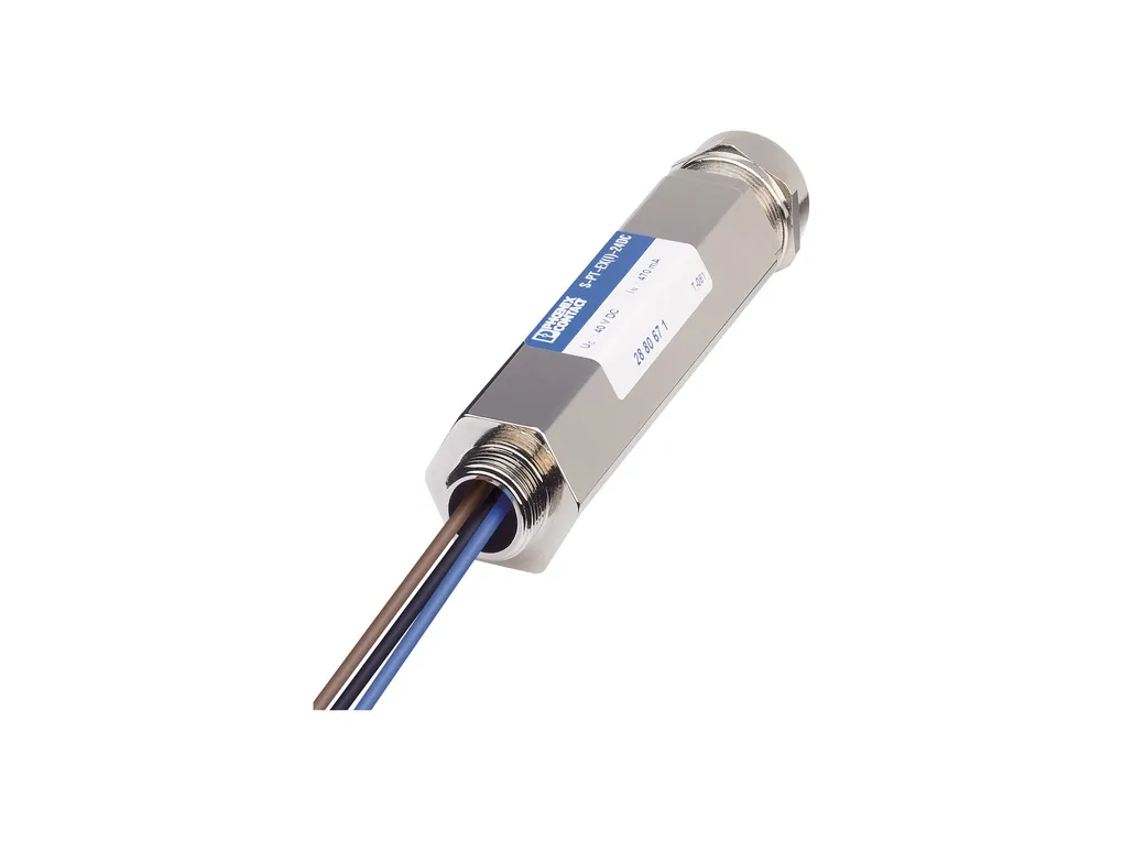
S-PT-EX(I)-24DC-3/4" - Surge protection device

Surge protection in the IP67 screw-on module for measuring sensors in intrinsically safe circuits, direct mounting with 3/4" NPT outer thread, cable gland for the signal cable, two-stage protective circuit. HART-compatible.
Cod. Articolo: 2882585
Cod. Fornitore: 2882585
PHOENIX CONTACT


Diminuisci la quantità
Aumenta la quantità
Caratteristiche Tecniche
Download
Caratteristiche Tecniche
NotesGeneral: When the bridge is disconnected, the shield connection is indirectly connected to the housing or reference potential.
Product propertiesIEC test classification: C1
C2
C3
D1
Type: Screw-in module
Product type: Surge protection for MCR technology
Product family: SURGETRAB
Number of positions: 3
Surge protection fault message: none
Wire pairs per module: 1
Insulation characteristics
Overvoltage category: III
Pollution degree: 2
Electrical propertiesNominal voltage UN: 24 VÂDC
Connection dataConnection method: Screw connection
Screw thread: M3
Tightening torque: 0.6 Nm
Conductor cross section flexible: 0.14 mm² ... 1.5 mm²
Conductor cross section rigid: 0.14 mm² ... 1.5 mm²
Conductor cross section AWG: 26 ... 16
Ex dataMaximum inner capacitance Ci: 2 nF
Max. internal inductance Li: 1 µH
Max. input current Ii: 350 mA (T4 / ≤Â50°C)
350 mA (T5 / ≤ 50°C)
350 mA (T6 / ≤ 50°C)
Max. input voltage Ui: 30 V
max. input power Pi: 3 W
Insulation voltage to ground: 500 VÂAC
Ambient temperature (operation): -40°C ... 50°C
Max. surface temperature: 135°C (T4)
100°C (T5)
85°C (T6)
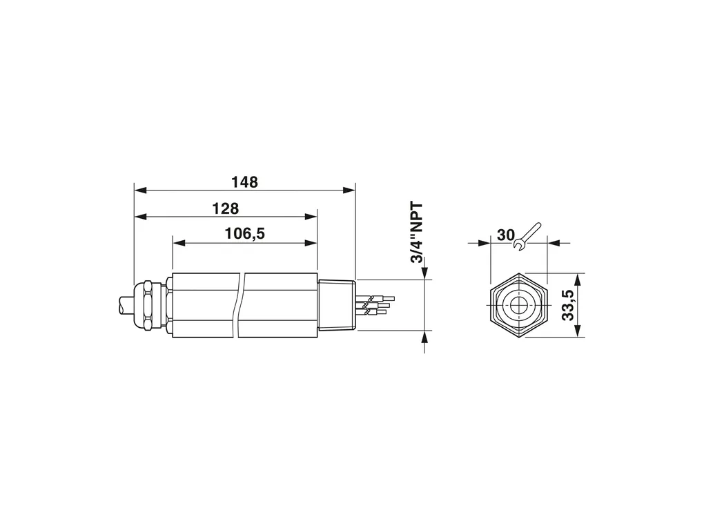
DimensionsDimensional drawing: https://dam-mdc.phoenixcontact.com/rendition/156443151564/5396ee696346bc4fb1835ec6e6f8616a/-S204x204-FJPG
Width: 33.5 mm
Height: 33.5 mm
Depth: 148 mm
Material specificationsColor: Steel / stainless steel
Housing surface material: nickel-plated
Housing material: Zinc die-cast, surface bronzed and nickel-plated
Mechanical propertiesMechanical data
Open side panel: No
Protective circuitDirection of action: Line-Line & Line-Earth Ground
Maximum continuous voltage UC: 30 VÂDC
21 VÂAC
Rated current: 350 mA (50°C)
Operating effective current IC at UC: ≤ 10 µA
Residual current IPE: ≤ 2 µA
Nominal discharge current In (8/20) µs (line-line): 10 kA
Nominal discharge current In (8/20) µs (line-ground): 10 kA (per path)
Nominal discharge current In (8/20)µs (shield-ground): 10 kA (optional)
Pulse discharge current Iimp (10/350)µs: 1 kA
Max. discharge current Imax (8/20) µs maximum (line-line): 10 kA
Max. discharge current Imax (8/20) µs maximum (line-earth): 10 kA (per path)
Discharge surge current Imax (8/20) µs maximum (shield-ground): 10 kA
Nominal pulse current Ian (10/1000) µs (line-line): 30 A
Nominal pulse current Ian (10/1000) µs (line-earth): 100 A (per path)
Nominal pulse current Ian (10/1000) µs (shield-ground): 100 A
Output voltage limitation at 1 kV/µs (line-line) spike: ≤ 50 V
Output voltage limitation at 1 kV/µs (line-earth) spike: ≤ 1.4 kV (Direct grounding)
Output voltage limitation at 1ÂkV/µs (shield-ground) spike: ≤ 600 V (optional)
Output voltage limitation at 1 kV/µs (line-line) static: ≤ 50 V
Output voltage limitation at 1 kV/µs (line-earth) static: ≤ 1.4 kV (Direct grounding)
Residual voltage at In (conductor-conductor): ≤ 50 V
Residual voltage with Ian (10/1000) µs (line-line): ≤ 50 V
Voltage protection level Up (line-line): ≤ 50 V (C1 - 0.5 kV / 250 A)
≤ 55 V (C1 - 1ÂkV / 500ÂA)
≤ 55 V (C2 - 2 kV/1 kA)
≤ 55 V (C2 - 10 kV / 5 kA)
≤ 50 V (C3 - 10ÂA)
≤ 50 V (C3 - 25ÂA)
≤ 80 V (D1 - 1 kA)
Voltage protection level Up (line-earth): ≤ 1.4 kV (C1 - 1ÂkV / 500ÂA)
≤ 1.4 kV (C2 - 2 kV/1 kA)
≤ 1.4 kV (C2 - 10 kV / 5 kA)
≤ 1.4 kV (C3 - 25ÂA)
≤ 1.4 kV (C3 - 100ÂA)
≤ 1.4 kV (D1 - 1 kA)
Voltage protection level Up (shield-ground): ≤ 600 V (C1 - 0.5 kV / 250 A)
≤ 650 V (C1 - 1ÂkV / 500ÂA)
≤ 650 V (C2 - 2 kV/1 kA)
≤ 650 V (C2 - 10 kV / 5 kA)
≤ 650 V (C3 - 10ÂA)
≤ 750 V (C3 - 25ÂA)
≤ 750 V (C3 - 100ÂA)
≤ 650 V (D1 - 1 kA)
Response time tA (line-line): ≤ 1 ns
Response time tA (line-earth): ≤ 100 ns
Response time tA (shield-ground): ≤ 100 ns
Input attenuation aE, sym.: typ. 0.5 dB (≤ 1 MHz / 50 Ω)
typ. 0.2 dB (≤ 400 kHz / 150 Ω)
Cut-off frequency fg (3ÂdB), sym. in 50ÂΩ system: typ. 6 MHz
Cut-off frequency fg (3ÂdB), sym. in 150ÂΩ system: typ. 2.5 MHz
Resistance per path: 2.2 Ω ±10Â%
Surge protection fault message: none
Impulse durability (line-line): C1 - 1ÂkV / 500ÂA
C2 - 10ÂkV / 5ÂkA
C3 - 25ÂA
D1 - 1ÂkA
Impulse durability (line-earth): C1 - 1ÂkV / 500ÂA
C2 - 10ÂkV / 5ÂkA
C3 - 100ÂA
D1 - 1ÂkA
Impulse durability (shield-ground): C1 - 1 ÂkV/500ÂA
C2 - 10ÂkV/5ÂkA
C3 - 100ÂA
D1 - 1ÂkA
Alternating current carrying capacity (line-earth): 10ÂA - 1Âs
Alternating current carrying capacity (shield-ground): 10ÂA - 1Âs
Environmental and real-life conditionsAmbient conditions
Degree of protection: IP67
Ambient temperature (operation): -40°C ... 50°C
Ambient temperature (storage/transport): -40°C ... 85°C
Altitude: ≤ 2000 m (amsl)
ApprovalsConformity/Approvals
ATEX: ïÃ‹œ II 1G Ex ia IIC T4...T6 Ga
IECEx: Ex ia IIC T4...T6 Ga
Standards and regulationsAir clearances and creepage distances
Standards/regulations: IEC 60664-1 / ENÂ60079-0 / ENÂ60079-11
Standards/specifications: ENÂ61643-21
ENÂ60079-0
ENÂ60079-11
IEC 60079-0
IEC 60079-11
Note: A2:2013
2018
2012
2017
2011
MountingMounting type: direct screw connection
Download
PER SCARICARE I DOCUMENTI E' NECESSARIO EFFETTUARE L'ACCESSO AL SITO

Approvals_01654.pdf

Approvals_01674.pdf

Approvals_01833.pdf

Approvals_01841.pdf

Certification_00276.pdf

Certification_00299.pdf

Flyer_00001.pdf

Flyer_00002.pdf

Manufacturer_declaration_00544.pdf

Manufacturer_declaration_02080.pdf

Manufacturer_declaration_15401.pdf

Package_slip_00431.pdf

Product_information_00033.pdf

Product_information_01014.pdf

Technical_drawing_39146.pdf