Automazione Industriale

Meccatronica

Sicurezza Industriale

Componenti Quadri

Sensori e Sistemi di Visione

Pneumatica

Network e Comunicazione

Cavi Speciali

Software di progettazione

Accedi ai servizi

Entra nella tua area riservata

Accedi ai servizi

Entra nella tua area riservata

PHOENIX CONTACT 2801164
PHOENIX CONTACTNon disponibile

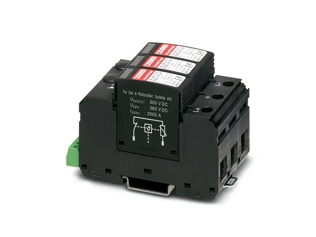
VAL-MS-T1/T2 600DC-PV/2+V-FM - Lightning/surge arrester type 1/2

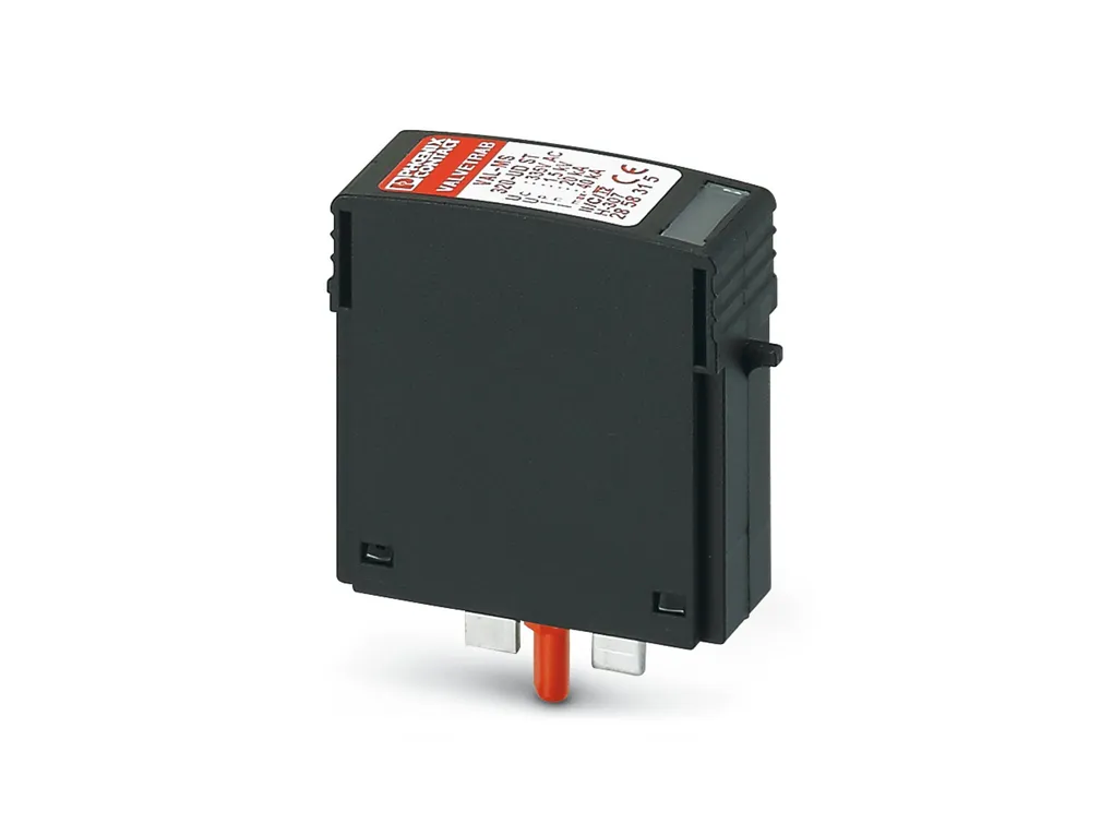
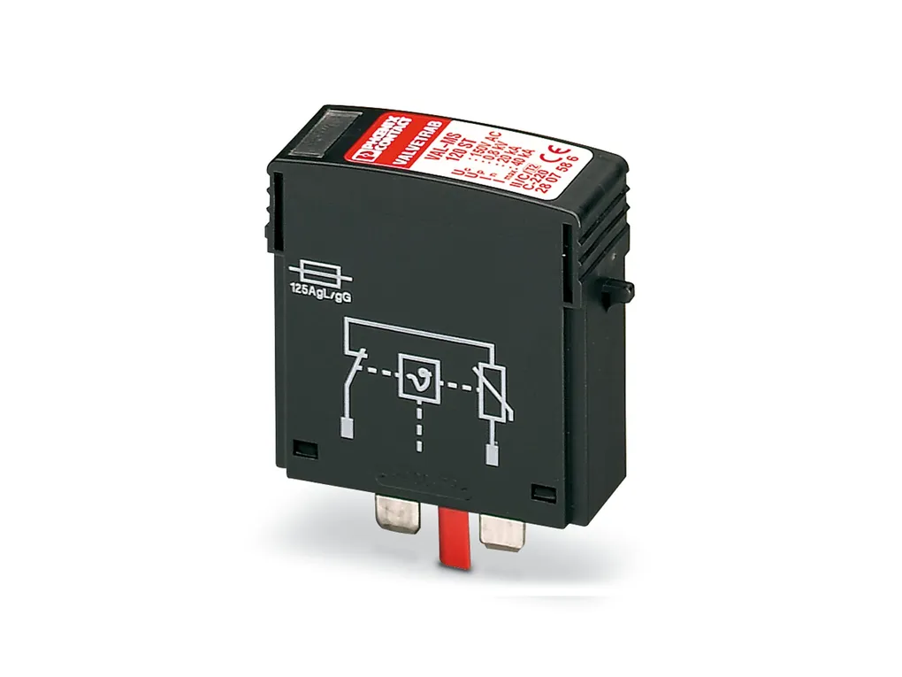
Lightning current arrester/surge protective device for 2-pos. isolated and grounded 600VDC PV voltage systems, for DIN rail mounting, 3-pos. base element with remote indication contact, three pluggable temperature-monitored protective elements, status message at each plug.
Cod. Articolo: 2801164
Cod. Fornitore: 2801164
PHOENIX CONTACT


Diminuisci la quantità
Aumenta la quantità
Caratteristiche Tecniche
Download
Caratteristiche Tecniche
NotesGeneral
Note: The device is intended for touch proof installation in a housing. Ensure that there is a gap of at least 8 mm between the active and grounded parts in the connection area.
Product propertiesIEC test classification: PV I / II
PV T1 / T2
EN type: T1 / T2
IEC power supply system: DC
Type: DIN rail module, two-section, divisible
Distance between live and grounded parts: 8 mm
Product type: PV arrester
Product family: VALVETRAB MS
Installation location: Interior
Installation location of the disconnect device: Internal
Accessibility: Accessible
Connection configuration: Y configuration
SPD failure behavior: OCFM (Open-Circuit Failure Mode)
Surge protection fault message: Optical, remote indicator contact
Insulation characteristics
Overvoltage category: III
Pollution degree: 2
Electrical propertiesIndicator/remote signaling
Connection name: Remote fault indicator contact
Switching function: Changeover contact
Operating voltage: 5 VÂAC ... 250 VÂAC
30 VÂDC
Operating current: 5 mA AC ... 1.5 A AC
1 AÂDC
Connection dataConnection method: Screw connection
Fork-type cable lug
Screw thread: M5
Tightening torque: 3 Nm (1.5Âmm² ... 16Âmm²)
4.5 Nm (25Âmm²Ãƒ‚...Â35Âmm²)
Stripping length: 16 mm
Conductor cross section flexible: 1.5 mm² ... 25 mm²
1.5 mm² ... 16 mm²
Conductor cross section rigid: 1.5 mm² ... 35 mm²
Conductor cross section AWG: 15 ... 2
Remote fault indicator contact
Connection method: Plug-in/screw connection via COMBICON
Screw thread: M2
Tightening torque: 0.25 Nm
Stripping length: 7 mm
Conductor cross section flexible: 0.14 mm² ... 1.5 mm²
Conductor cross section rigid: 0.14 mm² ... 1.5 mm²
Conductor cross section AWG: 28 ... 16
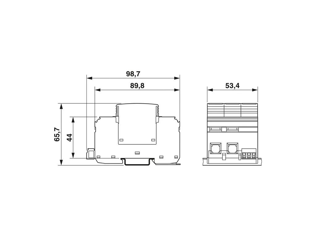
DimensionsDimensional drawing: https://dam-mdc.phoenixcontact.com/rendition/156443151564/0e4a0832d4206348bed6ca2ea11b5b69/-S204x204-FJPG
Width: 53.4 mm
Height: 98.7 mm
Depth: 65.7 mm (incl. DIN rail 7.5Âmm)
Horizontal pitch: 3 Div.
Material specificationsFlammability rating according to UL 94: V-0
CTI value of material: 600
Insulating material: PA 6.6-FR
PBT-FR
Material group: I
Housing material: PA 6.6-FR
PBT-FR
Mechanical propertiesMechanical data
Open side panel: No
Protective circuitMode of protection: (L+) - (L-)
(L+) - PE
(L-) - PE
Direction of action: (L+)-PE & (L-)-PE & (L+)-(L-)
Rated load current IL: 80 A
Residual current IPE: ≤ 20 µA DC
≤ 350 µA AC
Standby power consumption PC: ≤ 25 mVA
Nominal discharge current In (8/20) µs: 15 kA
Maximum discharge current Imax (8/20) µs: 40 kA
Impulse discharge current (10/350)µs, charge: 2.5 As
Impulse discharge current (10/350)µs, specific energy: 6.25 kJ/Ω
Impulse discharge current (10/350)µs, peak value limp: 5 kA
Total discharge current Itotal (8/20)µs: 40 kA
Total discharge current Itotal (10/350)µs: 7 kA
Voltage protection level Up: ≤ 2.6 kV
Residual voltage Ures: ≤ 2.6 kV (at In)
≤ 2 kV (at 5 kA)
≤ 2.3 kV (at 10 kA)
≤ 2.8 kV (at 20 kA)
≤ 3.1 kV (at 30 kA)
≤ 3.6 kV (at 40 kA)
Response time tA: ≤ 25 ns
PV protective circuit
Connection configuration: Y configuration
SPD failure behavior: OCFM (Open-Circuit Failure Mode)
Protective circuit DC voltage side (DC)
Open circuit voltage UOCSTC: ≤ 600 VÂDC
Maximum discharge current Imax (8/20) µs: 40 kA
Response time tA: ≤ 25 ns
Impulse discharge current (10/350)µs, charge: 2.5 As
Impulse discharge current (10/350)µs, specific energy: 6.25 kJ/Ω
Impulse discharge current (10/350)µs, peak value limp: 5 kA
Total discharge current Itotal (8/20)µs: 40 kA
Total discharge current Itotal (10/350)µs: 7 kA
Insulation resistance Riso: > 5 GΩ (at 500 V DC)
Nominal discharge current In (8/20) µs: 15 kA
Rated load current IL: 80 A
Continuous operating current ICPV: < 20 µA
Maximum continuous operating voltage UCPV: 720 VÂDC
Short-circuit current rating ISCPV: 2000 A
Residual voltage Ures: ≤ 2.6 kV (at In)
≤ 2 kV (at 5 kA)
≤ 2.3 kV (at 10 kA)
≤ 2.8 kV (at 20 kA)
≤ 3.1 kV (at 30 kA)
≤ 3.6 kV (at 40 kA)
Residual current IPE: ≤ 20 µA DC
≤ 350 µA AC
Voltage protection level Up: ≤ 2.6 kV
Standby power consumption PC: ≤ 25 mVA
Environmental and real-life conditionsAmbient conditions
Degree of protection: IP20 (only when all terminal points are used)
Ambient temperature (operation): -40°C ... 80°C
Ambient temperature (storage/transport): -40°C ... 80°C
Altitude: ≤ 2000 m (amsl)
Permissible humidity (operation): 5 % ... 95 %
Shock (operation): 60g (Half-sine / 11 ms / 3x ±X, ±Y, ±Z)
Vibration (operation): 7.5g (5-500 Hz/2.5 h/XYZ)
ApprovalsUL specifications
Maximum continuous operating voltage MCOV: 800 VÂDC
Short-circuit current rating (SCCR): 50 kA
Voltage protection rating VPR: 2 kV
Nominal discharge current In: 20 kA
Mode of protection: (L+) - (L-)
(L+) - G
(L-) - G
Nominal voltage: 800 VÂDC
Power distribution system: DCÂPV
SPD Type: 1
UL indicator/remote signaling
Operating voltage: 125 VÂAC
AC operating current: 1 A AC
UL connection data
Tightening torque: 30 lbf-in.
Conductor cross section AWG: 14 ... 2
Standards and regulationsStandards/specifications: ENÂ61643-31
IEC 61643-31
Note: 2019
2018
MountingMounting type: DIN rail: 35 mm
Download
PER SCARICARE I DOCUMENTI E' NECESSARIO EFFETTUARE L'ACCESSO AL SITO

Approvals_00272.pdf

Approvals_01874.pdf

Certification_00184.pdf

Flyer_00001.pdf

Flyer_00002.pdf

Manufacturer_declaration_00676.pdf

Manufacturer_declaration_02443.pdf

Manufacturer_declaration_04395.pdf

Package_slip_00537.pdf

Technical_drawing_38510.pdf