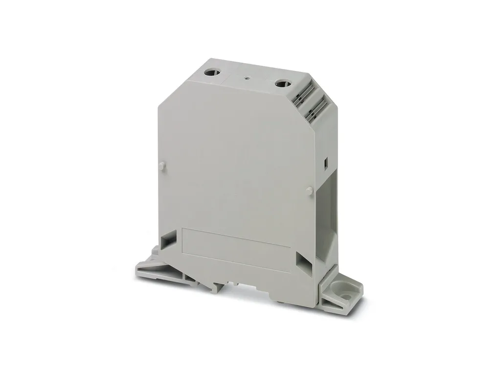
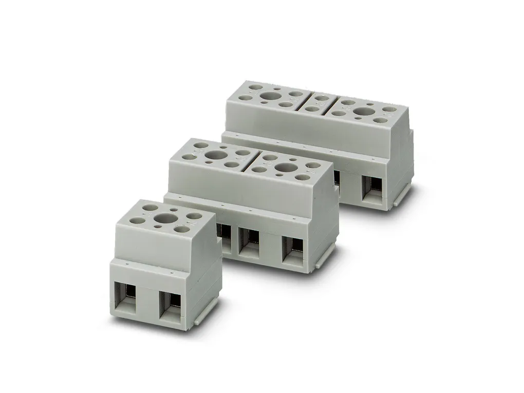
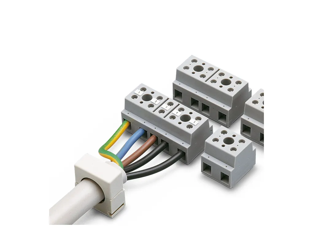
Device terminal block, nom. voltage: 800 V, nominal current: 57 A, number of connections: 6, number of positions: 3, connection method: Screw connection, Rated cross section: 10 mm2, cross section: 0.5 mm2-16 mm2, mounting type: direct screw connection, color: gray
Cod. Articolo: 2716716
Cod. Fornitore: 2716716
PHOENIX CONTACT
Caratteristiche Tecniche
Download
Caratteristiche Tecniche
Product properties
Product type: Feed-through terminal block Number of positions: 3 Number of connections: 6 Number of rows: 1 Potentials: 3 Insulation characteristics Overvoltage category: III Degree of pollution: 3
Electrical properties
Rated surge voltage: 8 kV Maximum power dissipation for nominal condition: 1.82 W
Connection data
Number of connections per level: 6 Nominal cross section: 10 mm² Screw thread: M4 Tightening torque: 1.5 ... 1.8 Nm Stripping length: 12 mm Internal cylindrical gage: A3 Connection in acc. with standard: IEC 60947-7-1 Conductor cross section rigid: 0.5 mm² ... 16 mm² Cross section AWG: 20 ... 6 (converted acc. to IEC) Conductor cross section flexible: 0.5 mm² ... 10 mm² Conductor cross section, flexible [AWG]: 20 ... 8 (converted acc. to IEC) Conductor cross-section flexible (ferrule without plastic sleeve): 0.5 mm² ... 16 mm² Flexible conductor cross section (ferrule with plastic sleeve): 0.5 mm² ... 16 mm² 2 conductors with same cross section, solid: 0.5 mm² ... 6 mm² 2 conductors with same cross section, flexible: 0.5 mm² ... 6 mm² 2 conductors with same cross section, flexible, with ferrule without plastic sleeve: 0.5 mm² ... 6 mm² 2 conductors with the same cross section, flexible, with TWIN ferrule with plastic sleeve: 0.5 mm² ... 6 mm² Nominal current: 57 A Maximum load current: 76 A (with 16 mm² conductor cross section) Nominal voltage: 800 V
Dimensions
Dimensional drawing: https://dam-mdc.phoenixcontact.com/rendition/156443151564/c54e8a792a8884458abba4eaf5115355/-S204x204-FJPG Width: 46 mm Height: 33 mm Depth: 31 mm Hole diameter: 4.2 mm
Material specifications
Color: gray Flammability rating according to UL 94: V2 Insulating material group: I Insulating material: PA Static insulating material application in cold: -40°C Temperature index of insulation material (DIN EN 60216-1 (VDE 0304-21)): 125°C Relative insulation material temperature index (Elec., UL 746 B): 125°C
Electrical tests
Surge voltage test Test voltage setpoint: 9.8 kV Result: Test passed Temperature-rise test Requirement temperature-rise test: Increase in temperature â¤45K Result: Test passed Short-time withstand current 10 mm²: 1.2 kA Short-time withstand current 16 mm²: 1.92 kA Power-frequency withstand voltage Test voltage setpoint: 2 kV Result: Test passed
Mechanical properties
Mechanical data Open side panel: No
Mechanical tests
Mechanical strength Result: Test passed Test for conductor damage and slackening Rotation speed: 10rpm Revolutions: 135 Conductor cross section/weight: 0.5 mm² / 0.3 kg 10 mm² / 2 kg 16 mm² / 2.9 kg Result: Test passed
Environmental and real-life conditions
Needle-flame test Time of exposure: 30 s Result: Test passed Ambient conditions Ambient temperature (storage/transport): -25°C ... 60°C (for a short time, not exceeding 24h, -60°C to +70°C) Ambient temperature (assembly): -5°C ... 70°C Ambient temperature (actuation): -5°C ... 70°C Permissible humidity (storage/transport): 30 % ... 70 %
Per fornire le migliori esperienze, utilizziamo tecnologie come i cookie per memorizzare e/o accedere alle informazioni del dispositivo. Il consenso a queste tecnologie ci permetterà di elaborare dati come il comportamento di navigazione o ID unici su questo sito. Non acconsentire o ritirare il consenso può influire negativamente su alcune caratteristiche e funzioni.
Funzionale
Sempre attivo
L'archiviazione tecnica o l'accesso sono strettamente necessari al fine legittimo di consentire l'uso di un servizio specifico esplicitamente richiesto dall'abbonato o dall'utente, o al solo scopo di effettuare la trasmissione di una comunicazione su una rete di comunicazione elettronica.
Preferenze
L'archiviazione tecnica o l'accesso sono necessari per lo scopo legittimo di memorizzare le preferenze che non sono richieste dall'abbonato o dall'utente.
Statistiche
L'archiviazione tecnica o l'accesso che viene utilizzato esclusivamente per scopi statistici.L'archiviazione tecnica o l'accesso che viene utilizzato esclusivamente per scopi statistici anonimi. Senza un mandato di comparizione, una conformità volontaria da parte del vostro Fornitore di Servizi Internet, o ulteriori registrazioni da parte di terzi, le informazioni memorizzate o recuperate per questo scopo da sole non possono di solito essere utilizzate per l'identificazione.
Marketing
L'archiviazione tecnica o l'accesso sono necessari per creare profili di utenti per inviare pubblicità, o per tracciare l'utente su un sito web o su diversi siti web per scopi di marketing simili.
Per fornire le migliori esperienze, utilizziamo tecnologie come i cookie per memorizzare e/o accedere alle informazioni del dispositivo. Il consenso a queste tecnologie ci permetterà di elaborare dati come il comportamento di navigazione o ID unici su questo sito. Non acconsentire o ritirare il consenso può influire negativamente su alcune caratteristiche e funzioni.
Funzionale
Sempre attivo
L'archiviazione tecnica o l'accesso sono strettamente necessari al fine legittimo di consentire l'uso di un servizio specifico esplicitamente richiesto dall'abbonato o dall'utente, o al solo scopo di effettuare la trasmissione di una comunicazione su una rete di comunicazione elettronica.
Preferenze
L'archiviazione tecnica o l'accesso sono necessari per lo scopo legittimo di memorizzare le preferenze che non sono richieste dall'abbonato o dall'utente.
Statistiche
L'archiviazione tecnica o l'accesso che viene utilizzato esclusivamente per scopi statistici.L'archiviazione tecnica o l'accesso che viene utilizzato esclusivamente per scopi statistici anonimi. Senza un mandato di comparizione, una conformità volontaria da parte del vostro Fornitore di Servizi Internet, o ulteriori registrazioni da parte di terzi, le informazioni memorizzate o recuperate per questo scopo da sole non possono di solito essere utilizzate per l'identificazione.
Marketing
L'archiviazione tecnica o l'accesso sono necessari per creare profili di utenti per inviare pubblicità, o per tracciare l'utente su un sito web o su diversi siti web per scopi di marketing simili.


 Non disponibile