Automazione Industriale

Meccatronica

Sicurezza Industriale

Componenti Quadri

Sensori e Sistemi di Visione

Pneumatica

Network e Comunicazione

Cavi Speciali

Software di progettazione

Accedi ai servizi

Entra nella tua area riservata

Accedi ai servizi

Entra nella tua area riservata

PHOENIX CONTACT 1932575
PHOENIX CONTACTNon disponibile

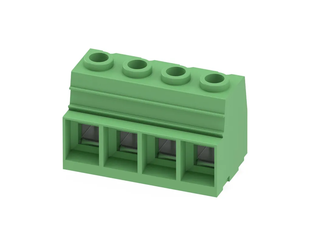
MKDSP 25/ 1-15,00-FL - PCB terminal block

PCB terminal block, nominal current: 125 A, rated voltage (III/2): 1000 V, nominal cross section: 35 mm2, number of potentials: 1, number of rows: 1, number of positions per row: 1, product range: MKDSP 25/..-FL, pitch: 15 mm, connection method: Screw connection with tension sleeve, screw head form: Z2L Slotted Pozidriv, mounting: Wave soldering, conductor/PCB connection direction: 0°, color: green, Pin layout: Linear pinning, Solder pin [P]: 4.5 mm, number of solder pins per potential: 4, type of packaging: packed in cardboard. Avoid placing permanent mechanical loads on the terminal
Cod. Articolo: 1932575

Cod. Fornitore: 1932575
PHOENIX CONTACT

Diminuisci la quantità
Aumenta la quantità
Caratteristiche Tecniche
Download
Caratteristiche Tecniche
Product propertiesType: Standard
Product line: COMBICON Terminals XL
Product type: Printed circuit board terminal
Product family: MKDSP 25/..-FL
Number of positions: 1
Pitch: 15 mm
Number of connections: 1
Number of rows: 1
Mounting flange: yes
Number of potentials: 1
Pin layout: Linear pinning
Solder pins per potential: 4
Electrical propertiesNominal current IN: 125 A
Nominal voltage UN: 1000 V
Degree of pollution: 3
Rated voltage (III/3): 1000 V
Rated surge voltage (III/3): 8 kV
Rated voltage (III/2): 1000 V
Rated surge voltage (III/2): 8 kV
Rated voltage (II/2): 1000 V
Rated surge voltage (II/2): 8 kV
Connection dataConnection technology
Type: Standard
Nominal cross section: 35 mm²
Conductor connection
Connection method: Screw connection with tension sleeve
Conductor cross section rigid: 0.5 mm² ... 35 mm²
Conductor cross section flexible: 0.5 mm² ... 35 mm²
Conductor cross section AWG: 20 ... 2
Conductor cross section flexible, with ferrule without plastic sleeve: 1 mm² ... 35 mm²
Conductor cross section, flexible, with ferrule, with plastic sleeve: 1.5 mm² ... 35 mm²
2 conductors with same cross section, solid: 0.5 mm² ... 6 mm²
2 conductors with same cross section, flexible: 0.5 mm² ... 6 mm²
2 conductors with same cross section, flexible, with ferrule without plastic sleeve: 0.5 mm² ... 4 mm²
2 conductors with the same cross section, flexible, with TWIN ferrule with plastic sleeve: 0.5 mm² ... 16 mm²
Stripping length: 18 mm
Tightening torque: 2.5 Nm ... 4.5 Nm
Information on the aluminum conductor
Cross section / torque / form of conductor: Cable cross section:35 mm²; Torque:4.5 Nm; Form of cable:round, single-strand, class 1(re)
Specification: DINVDE0276-603 (VDE0276-603):2010-03
Note on conductor pretreatment: The following measures are required for durable and reliable contacting of the aluminum conductor: the stripped end of the aluminum conductor must be separated from the oxide layer using a blade, and immediately dipped in non-acid and non-alkali Vaseline. The pretreatment must be repeated when connecting the conductors anew.
MountingMounting type: Wave soldering
Pin layout: Linear pinning
Drive form screw head: Slotted Pozidriv(Z2L)
Connection method: Screw connection with tension sleeve
Processing notes
Process: Wave soldering
Material specificationsMaterial data - contact
Note: WEEE/RoHS-compliant, free of whiskers according to IEC 60068-2-82/JEDEC JESD 201
Contact material: Cu alloy
Surface characteristics: Tin-plated
Metal surface terminal point (top layer): Tin (5 - 7 µm Sn)
Metal surface soldering area (top layer): Tin (5 - 7 µm Sn)
Material data - housing
Color (Housing): green (6021)
Insulating material: PA
Insulating material group: I
CTI according to IEC 60112: 600
Flammability rating according to UL 94: V0
Glow wire flammability index GWFI according to EN60695-2-12: 850
Glow wire ignition temperature GWIT according to EN60695-2-13: 775
Temperature for the ball pressure test according to EN60695-10-2: 125°C
NotesGeneral: The single-position PCB terminal block can be used for voltages up to 1500V (DC) and 1000V (AC). The relevant device standard and the appropriate required air clearances and creepage distances should be observed following installation
DimensionsDimensional drawing: https://dam-mdc.phoenixcontact.com/rendition/156443151564/158b0afe23d1ab408f646eacfe25f655/-S204x204-FJPG
Pitch: 15 mm
Width [w]: 30 mm
Height [h]: 43.5 mm
Length [l]: 31 mm
Installed height: 39 mm
Solder pin length [P]: 4.5 mm
Pin dimensions: 1.2 x 1.2 mm
PCB design
Hole diameter: 1.6 mm
Electrical testsAir clearances and creepage distances |
Specification: IEC 60664-1:2007-04
Insulating material group: I
Comparative tracking index (IEC 60112): CTI 600
Rated insulation voltage (III/3): 1000 V
Rated surge voltage (III/3): 8 kV
minimum clearance value - non-homogenous field (III/3): 8 mm
minimum creepage distance (III/3): 12.5 mm
Rated insulation voltage (III/2): 1000 V
Rated surge voltage (III/2): 8 kV
minimum clearance value - non-homogenous field (III/2): 8 mm
minimum creepage distance (III/2): 8 mm
Rated insulation voltage (II/2): 1000 V
Rated surge voltage (II/2): 8 kV
minimum clearance value - non-homogenous field (II/2): 8 mm
minimum creepage distance (II/2): 8 mm
Environmental and real-life conditionsAmbient conditions
Ambient temperature (operation): -40°C ... 100°C (Depending on the current carrying capacity/derating curve)
Ambient temperature (storage/transport): -40°C ... 70°C
Relative humidity (storage/transport): 30 % ... 70 %
Ambient temperature (assembly): -5°C ... 100°C
Packaging specificationsType of packaging: packed in cardboard
Outer packaging type: Carton
Download
PER SCARICARE I DOCUMENTI E' NECESSARIO EFFETTUARE L'ACCESSO AL SITO

Approvals_00394.pdf

Approvals_00420.pdf

Manufacturer_declaration_05483.pdf

Technical_drawing_33314.pdf

Altri prodotti correlati

Di seguito alcuni articoli correlati a quello che stai vedendo