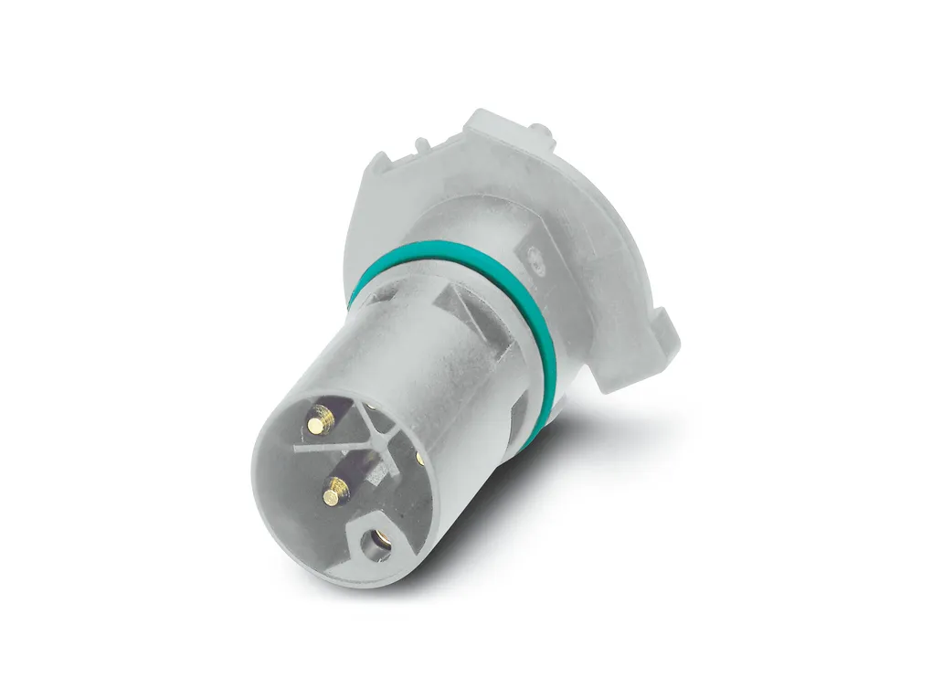
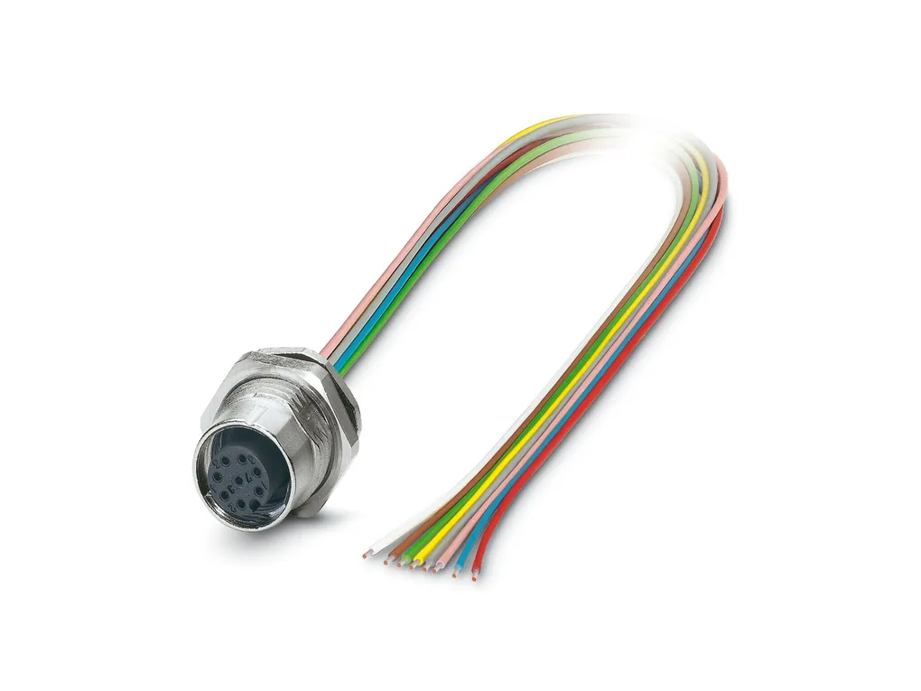
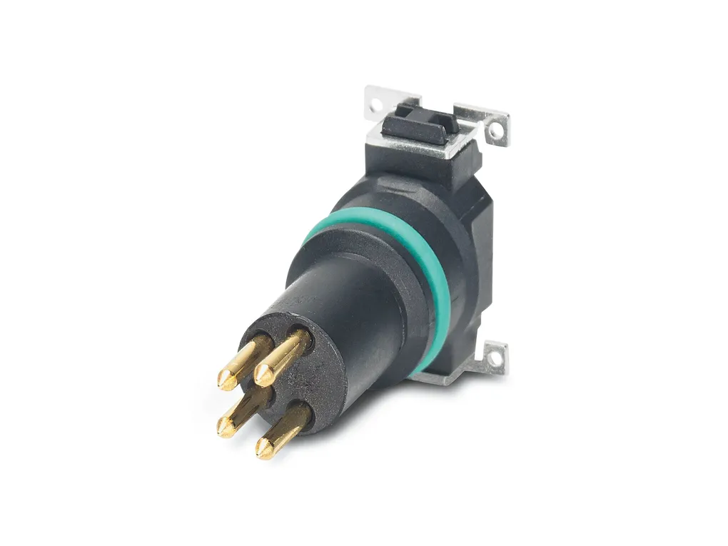
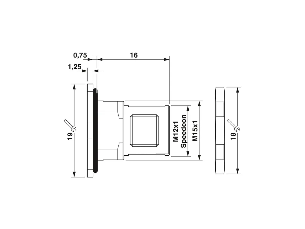
Housing screw connection, Pin, M12-SPEEDCON, Rear mounting, M15 x 1, Alternative product in accordance with RoHS II without Exemption6c (Pb<0.1%) item no.: 1239054
Cod. Articolo: 1414002
Cod. Fornitore: 1414002
PHOENIX CONTACT
Caratteristiche Tecniche
Download
Caratteristiche Tecniche
Notes
General: The electrical and mechanical data specified assume that the connector pair is correctly locked and mounted. If the connector is unlocked and if there is a danger of contamination, the connector must be sealed using a protective cap > IP54. Influences arising from litz wires, cables or PCB assembly must also be taken into consideration. Lock nut is included in the scope of delivery
Product properties
Product type: Panel mounting base Thread type: M12
Material specifications
Material: Brass, nickel-plated Zinc die-cast (nickel-plated) Seal material: FKM Material for screw connection: Zinc die-cast, nickel-plated
Connector
Connection 1 Head design: Pin Head thread type: M12 Head locking type: SPEEDCON
Mechanical properties
Mechanical data Insertion/withdrawal cycles: > 100
Environmental and real-life conditions
Ambient conditions Degree of protection (when plugged in): IP67 (correctly plugged in and locked) Degree of protection: IP67 (correctly plugged in and locked) IP67, when in locked state Ambient temperature (operation): -25°C ... 85°C (Plug / socket) -40°C ... 85°C (without mechanical actuation)
Standards and regulations
M12 Standard designation: M12 connector Standards/specifications: IEC 61076-2-101 Note: In line with
Mounting
Mounting type: Rear mounting M15 x 1 Spacing between the top edge of the PCB and the back of the front plate: 6 mm Assembly instructions: Spacing between the top edge of the PCB and the back of the front plate: 6 mm
Per fornire le migliori esperienze, utilizziamo tecnologie come i cookie per memorizzare e/o accedere alle informazioni del dispositivo. Il consenso a queste tecnologie ci permetterà di elaborare dati come il comportamento di navigazione o ID unici su questo sito. Non acconsentire o ritirare il consenso può influire negativamente su alcune caratteristiche e funzioni.
Funzionale
Sempre attivo
L'archiviazione tecnica o l'accesso sono strettamente necessari al fine legittimo di consentire l'uso di un servizio specifico esplicitamente richiesto dall'abbonato o dall'utente, o al solo scopo di effettuare la trasmissione di una comunicazione su una rete di comunicazione elettronica.
Preferenze
L'archiviazione tecnica o l'accesso sono necessari per lo scopo legittimo di memorizzare le preferenze che non sono richieste dall'abbonato o dall'utente.
Statistiche
L'archiviazione tecnica o l'accesso che viene utilizzato esclusivamente per scopi statistici.L'archiviazione tecnica o l'accesso che viene utilizzato esclusivamente per scopi statistici anonimi. Senza un mandato di comparizione, una conformità volontaria da parte del vostro Fornitore di Servizi Internet, o ulteriori registrazioni da parte di terzi, le informazioni memorizzate o recuperate per questo scopo da sole non possono di solito essere utilizzate per l'identificazione.
Marketing
L'archiviazione tecnica o l'accesso sono necessari per creare profili di utenti per inviare pubblicità, o per tracciare l'utente su un sito web o su diversi siti web per scopi di marketing simili.
Per fornire le migliori esperienze, utilizziamo tecnologie come i cookie per memorizzare e/o accedere alle informazioni del dispositivo. Il consenso a queste tecnologie ci permetterà di elaborare dati come il comportamento di navigazione o ID unici su questo sito. Non acconsentire o ritirare il consenso può influire negativamente su alcune caratteristiche e funzioni.
Funzionale
Sempre attivo
L'archiviazione tecnica o l'accesso sono strettamente necessari al fine legittimo di consentire l'uso di un servizio specifico esplicitamente richiesto dall'abbonato o dall'utente, o al solo scopo di effettuare la trasmissione di una comunicazione su una rete di comunicazione elettronica.
Preferenze
L'archiviazione tecnica o l'accesso sono necessari per lo scopo legittimo di memorizzare le preferenze che non sono richieste dall'abbonato o dall'utente.
Statistiche
L'archiviazione tecnica o l'accesso che viene utilizzato esclusivamente per scopi statistici.L'archiviazione tecnica o l'accesso che viene utilizzato esclusivamente per scopi statistici anonimi. Senza un mandato di comparizione, una conformità volontaria da parte del vostro Fornitore di Servizi Internet, o ulteriori registrazioni da parte di terzi, le informazioni memorizzate o recuperate per questo scopo da sole non possono di solito essere utilizzate per l'identificazione.
Marketing
L'archiviazione tecnica o l'accesso sono necessari per creare profili di utenti per inviare pubblicità, o per tracciare l'utente su un sito web o su diversi siti web per scopi di marketing simili.


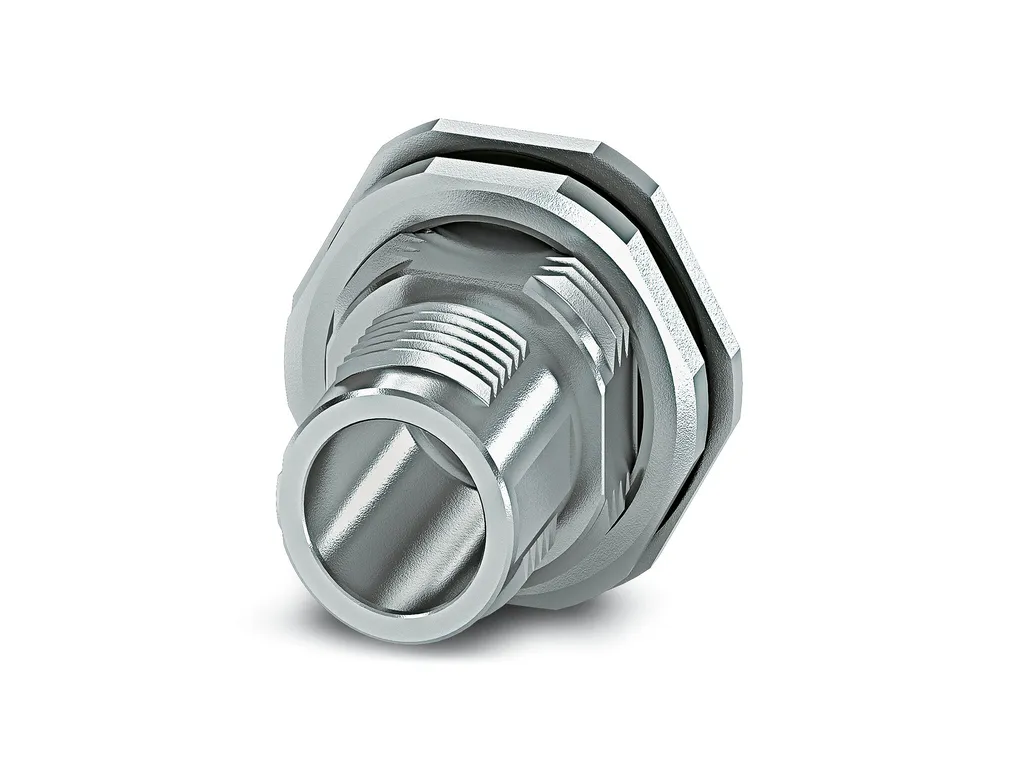
 Non disponibile