| Notes | Utilization restriction
EMC note: EMC: class A product, see manufacturer's declaration in the download area
|
| Product properties | Product type: Temperature transmitter
Product family: MACX Analog
Application: Temperature
No. of channels: 1
Type: Ex i signal conditioners with SIL functional safety
Configuration: Software
Insulation characteristics: GBÃStandard
Overvoltage category: II
Pollution degree: 2
|
| Electrical properties | No. of channels: 1
Electrical isolation: 3-way isolation
Electrical isolation between input and output: No
Cold point error, max.: ñ 2 K
Step response (0ââ¬Ã¢99%): 1 s
ââ°¤ 1.7 s
Temperature coefficient, typical: 0.01 %/K
Transmission error, typical: 0.1 % (For full identification of transmission errors, see the data sheet)
Electrical isolation Input/output/power supply
Rated insulation voltage: 300 Vrms
Test voltage: 2.5 kV AC (50ÃHz, 60Ãs)
Insulation: Safe isolation in accordance with IEC/ENÃ61010-1
Electrical isolation Input/output
Electrical isolation: 375 V (Peak value in accordance with IEC/EN 60079-11)
Electrical isolation Input/power supply
Electrical isolation: 375 V (Peak value in accordance with IEC/EN 60079-11)
Supply
Nominal supply voltage: 24 VÃDC
Supply voltage range: 19.2 VÃDC ... 30 VÃDC (24ÃVÃDC, -20Ã%Ã...Ã+25Ã%)
Max. current consumption: < 40 mA (24ÃVÃDC)
Power dissipation: ââ°¤ 0.76 W
Power consumption: ââ°¤ 1 W
|
| Input data | Signal
Number of inputs: 1
Input signal: Temperature
Voltage
Measurement
Description of the input: Intrinsically safe
Sensor types that can be used (TC): B, E, J, K, N, R, S, T, L, U, C, D, A-1, A-2, A-3, M, Lr
Temperature measuring range: -250°C ... 2500°C (Range depending on the sensor type)
Min. 50ÃK with thermocouple, 10%Ãof the nominal span of the respective range with mV sources
Sensor type:: 500°C ... 1820°C
-230°C ... 1000°C
-210°C ... 1200°C
-250°C ... 1372°C
-200°C ... 1300°C
-50°C ... 1768°C
-50°C ... 1768°C
-200°C ... 400°C
-200°C ... 900°C
-200°C ... 600°C
0°C ... 2315°C
0°C ... 2315°C
0°C ... 2500°C
0°C ... 1800°C
0°C ... 1800°C
-200°C ... 100°C
-200°C ... 800°C
Linear mV signal range: -1000 mV ... 1000 mV
|
| Output data | Signal: Current
Number of outputs: 1
Configurable/programmable: Yes
Current output signal: 0 mA ... 20 mA
4 mA ... 20 mA (SIL)
Load/output load current output: ââ°¤ 600 é
Output ripple (current): < 15 õAPP
< 10 õArms
Behavior in the event of a sensor error: As per NE 43 or can be freely defined
|
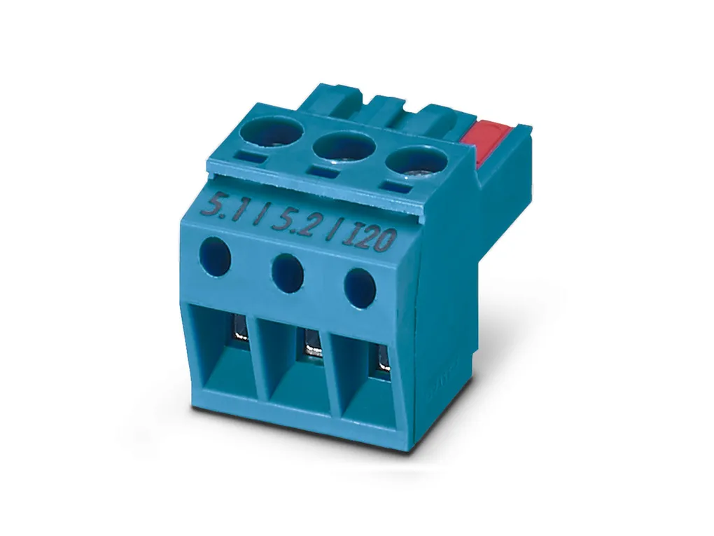
| Connection data | Connection method: Screw connection
Stripping length: 7 mm
Screw thread: M3
Conductor cross section rigid: 0.2 mm² ... 2.5 mm²
Conductor cross section flexible: 0.2 mm² ... 2.5 mm²
Conductor cross section AWG: 24 ... 14
Tightening torque: 0.5 Nm ... 0.6 Nm
Test socket
Max. diameter: 2 mm
|
| Ex data | Ex installation (EPL): Gc
Div.Ã2
Ex i circuits (EPL): Ga
Da
Ma
Div.Ã1
Safety data: Terminals: 4.1, 4.2, 5.1, 5.2
Max. internal capacitance Ci: 44 nF
Max. output voltage Uo: 6 V
Max. output current Io: 4.3 mA (mV)
7.1 mA (TC with internal cold junction compensation)
16.8 mA (TC with external cold junction, TC and cold junction connected)
Max. output power Po: 25.2 mW (Linear)
Safety-related maximum voltage Um: 253 VÃAC
125 VÃDC
30 VÃDC (ZoneÃ2: 3.1, 3.2)
IIA/I (simple circuit): Max. external inductivity Lo / Max. external capacitance Co: 850 mH / 1000 õF
IIB/IIIC (simple circuit): Max. external inductivity Lo / Max. external capacitance Co: 460 mH / 1000 õF
IIC (simple circuit): Max. external inductivity Lo / Max. external capacitance Co: 100 mH / 40 õF
IIB/IIA (mixed circuit): Max. external inductivity Lo / Max. external capacitance Co: 100 mH / 950 nF, 50 mH / 950 nF, 5 mH / 950 nF, 1 mH / 950 nF
IIIC/I (mixed circuit): Max. external inductivity Lo / Max. external capacitance Co: 100 mH / 950 nF, 50 mH / 950 nF, 5 mH / 950 nF, 1 mH / 950 nF
IIC (mixed circuit): Max. external inductivity Lo / Max. external capacitance Co: 100 mH / 555 nF, 50 mH / 555 nF, 5 mH / 555 nF, 1 mH / 555 nF, 10 õH / 555 nF
|
| Signaling | Status display: Green LED (supply voltage)
Red LED, flashing 2.4ÃHz (cable error, sensor error on input or output, ERR)
Red LED, flashing 1.2ÃHz (service operation, ERR)
Red LED, permanently on (module error, ERR)
|
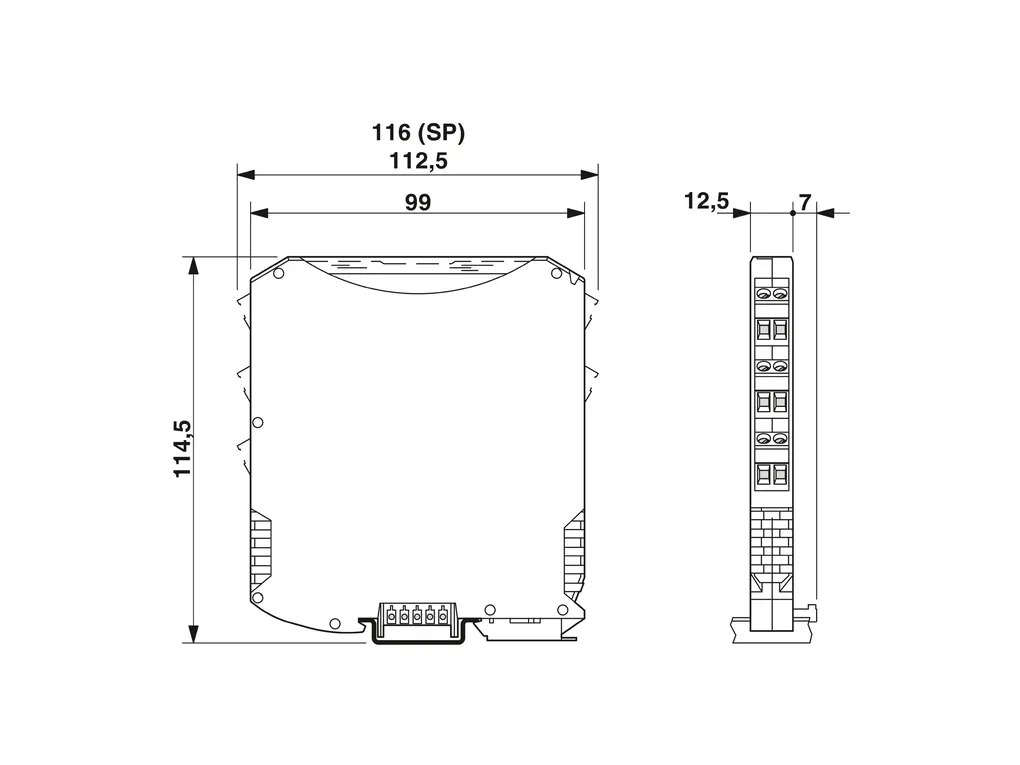
| Dimensions | Dimensional drawing: https://dam-mdc.phoenixcontact.com/rendition/156443151564/d4485e18fd60154ba93005f91a55c68d/-S204x204-FJPG
Width: 12.5 mm
Height: 112.5 mm
Depth: 113.7 mm
Depth NSÃ35/7,5: 114.5 mm (Snapped onto DIN rail NSÃ35/7,5 in accordance with ENÃ60715)
|
| Material specifications | Flammability rating according to UL 94: V0 (Housing)
Housing material: PA 6.6-FR
|
| Environmental and real-life conditions | Ambient conditions
Degree of protection: IP20
Ambient temperature (operation): -40°C ... 70°C (Any mounting position)
Ambient temperature (storage/transport): -40°C ... 80°C
Permissible humidity (operation): 5 % ... 95 % (non-condensing)
Altitude range (ââ°¤ 2000 m)
Altitude: ââ°¤ 2000 m (The technical data refers to altitudes ââ°¤2000Ãm above mean sea level. For altitudes >2000Ãm above mean sea level, refer to the data sheet.)
Ambient temperature (operation): -40°C ... 70°C
Test voltage: 2.5 kV
Rated insulation voltage: 300 Vrms (IEC/ENÃ60079-11)
375 VPP (IEC/ENÃ60079-11)
Altitude range (ââ°¤ 3000 m)
Height range: > 2000 m ... 3000 m
Ambient temperature (operation): -40°C ... 60°C
Test voltage: 2.25 kV
Safety-related maximum voltage Um: 190 VÃAC
110 VÃDC
Rated insulation voltage: 190 Vrms (IEC/ENÃ60079-11)
Altitude range (ââ°¤ 4000 m)
Height range: > 3000 m ... 4000 m
Ambient temperature (operation): -40°C ... 55°C
Test voltage: 2 kV
Safety-related maximum voltage Um: 60 V AC/DC
Rated insulation voltage: 60 Vrms (IEC/ENÃ60079-11)
Altitude range (ââ°¤ 5000 m)
Height range: > 4000 m ... 5000 m
Ambient temperature (operation): -40°C ... 49°C
Test voltage: 1.75 kV
Safety-related maximum voltage Um: 60 V AC/DC
Rated insulation voltage: 60 Vrms (IEC/ENÃ60079-11)
|
| Approvals | CE
Certificate: CE-compliant
Note: and ENÃ61326
ATEX
Identification: ïà I (M1) [Ex ia Ma] I
ïà II (1) G [Ex ia Ga] IIC
ïà II (1) D [Ex ia Da] IIIC
ïà II 3(1) G Ex ec ic [ia Ga] IIC T4 Gc
Certificate: IBExU19ATEX1006 X
UKCAÃExÃ(UKEX)
Identification: ïà I (M1) [Ex ia Ma] I
ïà II (1) G [Ex ia Ga] IIC
ïà II (1) D [Ex ia Da] IIIC
ïà II 3 (1) G Ex ec ic [ia Ga] IIC T4 Gc
Certificate: CML 22UKEX3531X
IECEx
Identification: [Ex ia Ma] I
[Ex ia Ga] IIC
[Ex ia Da] IIIC
Ex ec ic [ia Ga] IIC T4 Gc
Certificate: IECEx IBE 19.0001 X
CCCÃ/ÃChina-Ex
Identification: [Ex ia Ga] IIC
[Ex iaD]
Ex nA ic [ia Ga] IIC T4 Gc
Certificate: NEPSIÃGYJ20.1305X
UL, USA/Canada
Identification: UL 61010 Listed
Class I Div 2; IS for Class I, II, III Div 1
Certificate: ïâ¢, C.D.-No 83104549
Shipbuilding approval
Certificate: DNV GL TAA00000AG
Safety Integrity Level (SIL, IEC 61508)
Identification: 2
INMETRO
Identification: [Ex ia Ma] I
[Ex ia Ga] IIC
[Ex ia Da] IIIC
Ex ec ic [ia Ga] IIC T4 Gc
Certificate: DNV 21.0064 X
EACÃEx
Identification: ïÃâ [Ex ia Ga] IIC
ïÃâ [Ex ia Da] IIIC
Certificate: RU C-DE.AB72.B.00093/19
DNV GL data
Temperature: B
Humidity: B
Vibration: A
EMC: B
Enclosure: Required protection according to the Rules shall be provided upon installation on board
|
| EMC data | Noise immunity: EN 61000-6-2
Note: When being exposed to interference, there may be minimal deviations.
Electromagnetic compatibility: Conformance with EMC directive
Noise emission: EN 61000-6-4
Electromagnetic HF field
Designation: Electromagnetic RF field
Standards/regulations: ENÃ61000-4-3
Typical deviation from the measuring range final value: 1 %
Fast transients (burst)
Designation: Fast transients (burst)
Standards/regulations: ENÃ61000-4-4
Typical deviation from the measuring range final value: 1 %
Conducted interference
Designation: Conducted interferences
Standards/regulations: ENÃ61000-4-6
Typical deviation from the measuring range final value: 1 %
|
| Standards and regulations | Electrical isolation: 3-way isolation
GBÃStandard
Standards/regulations: GBÃ3626.20
GBÃ3836.1
GBÃ3836.4
GBÃ3836.8
GBÃ12476.1
GBÃ12476.4
|
| Mounting | Mounting type: DIN rail mounting
|
 Non disponibile


